Due Sunday, December 10 at 11:59 PM
By the time you have completed this work, you should be able to:
For this week, you will translate a word problem into a diagram representing a finite state machine (FSM). From there, you will provide enough detail to implement the finite state machine as a circuit. There are multiple tasks for this assignment. While each task can be completed independently of each other, they progressively build in difficulty, so it is recommended to complete them in order. The tasks are listed below:
010110In this task, you will design a FSM which controls a seven segment display. Throughout this task, we will be using a seven segment display similar to the following (provided by Wikipedia):
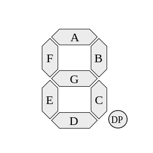
Each of the letters in the above diagram refers to an individual segment of the display.
The identifier “DP” refers to the decimal point, which will not be used in this task.
The display allows segments to be individiually turned on and off, allowing for different numbers to be represented by selectively enabling or disabling the right segments.
The table below illustrates which segments need to be enabled for the corresponding decimal digit to be represented:
| Number | Segments to Enable |
|---|---|
0 |
A, B, C, D, E, F |
1 |
B, C |
2 |
A, B, G, E, D |
3 |
A, B, G, C, D |
4 |
F, B, G, C |
5 |
A, F, G, C, D |
6 |
A, F, G, E, C, D |
7 |
A, B, C |
8 |
A, B, C, D, E, F, G |
9 |
A, B, C, D, F, G |
The FSM for this task should alternate between displaying 1, 2, 4, and 8, in that order.
In order to accomplish this, the inputs to the seven segment display will be treated as outputs of your FSM.
That is, your FSM will output the appropriate values of A, B, C, D, E, F, and G in order to represent the numbers of interest.
This overall task is separated into a series of questions.
Draw the finite state machine corresponding to this task.
If you are submitting this online, put this diagram into a file named “display.jpg”.
How many latches/flip-flops do you need to implement this state machine?
(Hint: this corresponds to the number of bits necessary in order to encode all possible states uniquely.)
If you are submitting this online, put this into a file named “display.txt”.
This will be read by hand, so don't worry about the formatting (as long as it is clear and unambiguous).
Draw a single truth table representing the behavior of the state machine.
Be sure to label your states in binary.
Your table should have inputs corresponding to whatever state you are in.
The output corresponds to the next state to enter for a given input state, along with the values for the seven segment display.
If you are submitting this online, add this to your “display.txt” file.
This will be read by hand, so don't worry about the formatting (as long as it is clear and unambiguous).
Using a Karnaugh map, determine the minimal sum-of-products formula corresponding to output A (corresponding to input A of the seven-segment display.
Where appropriate, use don't cares in the map (note that there may be no appropriate uses of don't cares).
If you are submitting this online, add this to your “display.txt” file.
This will be read by hand, so don't worry about the formatting (as long as it is clear and unambiguous).
Using a Karnaugh map, determine the minimal sum-of-products formula corresponding to the rightmost bit of the next state.
Where appropriate, use don't cares in the map (note that there may be no appropriate uses of don't cares).
If you are submitting this online, add this to your “display.txt” file.
This will be read by hand, so don't worry about the formatting (as long as it is clear and unambiguous).
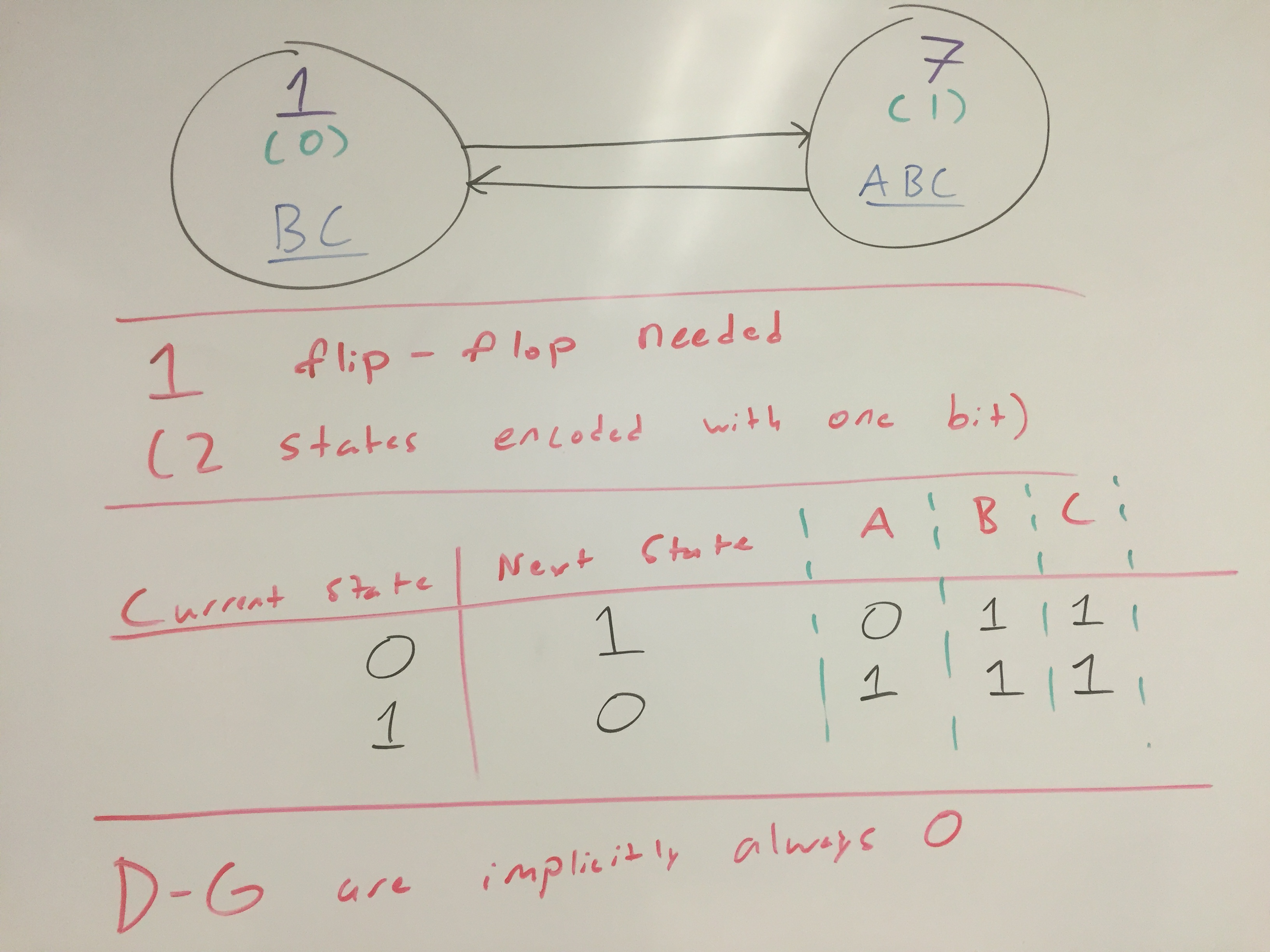
To help with questions 1-3, a solution to a very similar problem is provided here.
In this example, the FSM alternates between displaying 1 and 7.
The diagram has these major components:
1 or a 7.
7 (binary 1), the output of the state is ABC, meaning segments A, B, and C in the seven-segment display should be activated.
In conjunction, when these three segments are lit up, they display 7.
01
In this task, you will design a FSM which will set a particular output U to 1 each time 01 is encountered in a stream of inputs.
Inputs are specified one at a time, and are represented by the variable I.
To illustrate, consider the following example, which shows different values of U and I over time, where each cell is separated by a clock tick:
I |
1 |
0 |
1 |
1 |
0 |
0 |
1 |
1 |
0 |
1 |
0 |
1 |
1 |
U |
0 |
0 |
0 |
1 |
0 |
0 |
0 |
1 |
0 |
0 |
1 |
0 |
1 |
In the above example, it may appear that the output of U is delayed with respect to input I.
That is, when the 1 is 01 is encountered, it's not until the next clock tick that U is set to 1.
This is actually expected behavior, as it reflects the fact that first the circuit reads 1, and then it moves into a state that reports U = 1.
The key difference between this task and Task 1 is that this circuit takes an auxilliary input, which changes over time. As such, the finite state machine diagrams you draw should reflect changes in behavior, depending on which inputs are provided. Ultimately, this means that your FSMs will transition to different states depending on the inputs provided.
This overall task is separated into a series of questions.
Draw the finite state machine corresponding to this task.
If you are submitting this online, put this diagram into a file named “sequence1.jpg”.
How many latches/flip-flops do you need to implement this state machine?
(Hint: this corresponds to the number of bits necessary in order to encode all possible states uniquely.)
If you are submitting this online, put this into a file named “sequence1.txt”.
This will be read by hand, so don't worry about the formatting (as long as it is clear and unambiguous).
Draw a single truth table representing the behavior of the state machine.
Be sure to label your states in binary.
Your table should have inputs corresponding to whatever state you are in, along with I.
The output corresponds to the next state to enter for a given input state, along with U.
If you are submitting this online, add this to your “sequence1.txt” file.
This will be read by hand, so don't worry about the formatting (as long as it is clear and unambiguous).
Using a Karnaugh map, determine the minimal sum-of-products formula corresponding to output U.
Where appropriate, use don't cares in the map (note that there may be no appropriate uses of don't cares).
If you are submitting this online, add this to your “sequence1.txt” file.
This will be read by hand, so don't worry about the formatting (as long as it is clear and unambiguous).
Using a Karnaugh map, determine the minimal sum-of-products formula corresponding to the rightmost bit of the next state.
Where appropriate, use don't cares in the map (note that there may be no appropriate uses of don't cares).
If you are submitting this online, add this to your “sequence1.txt” file.
This will be read by hand, so don't worry about the formatting (as long as it is clear and unambiguous).
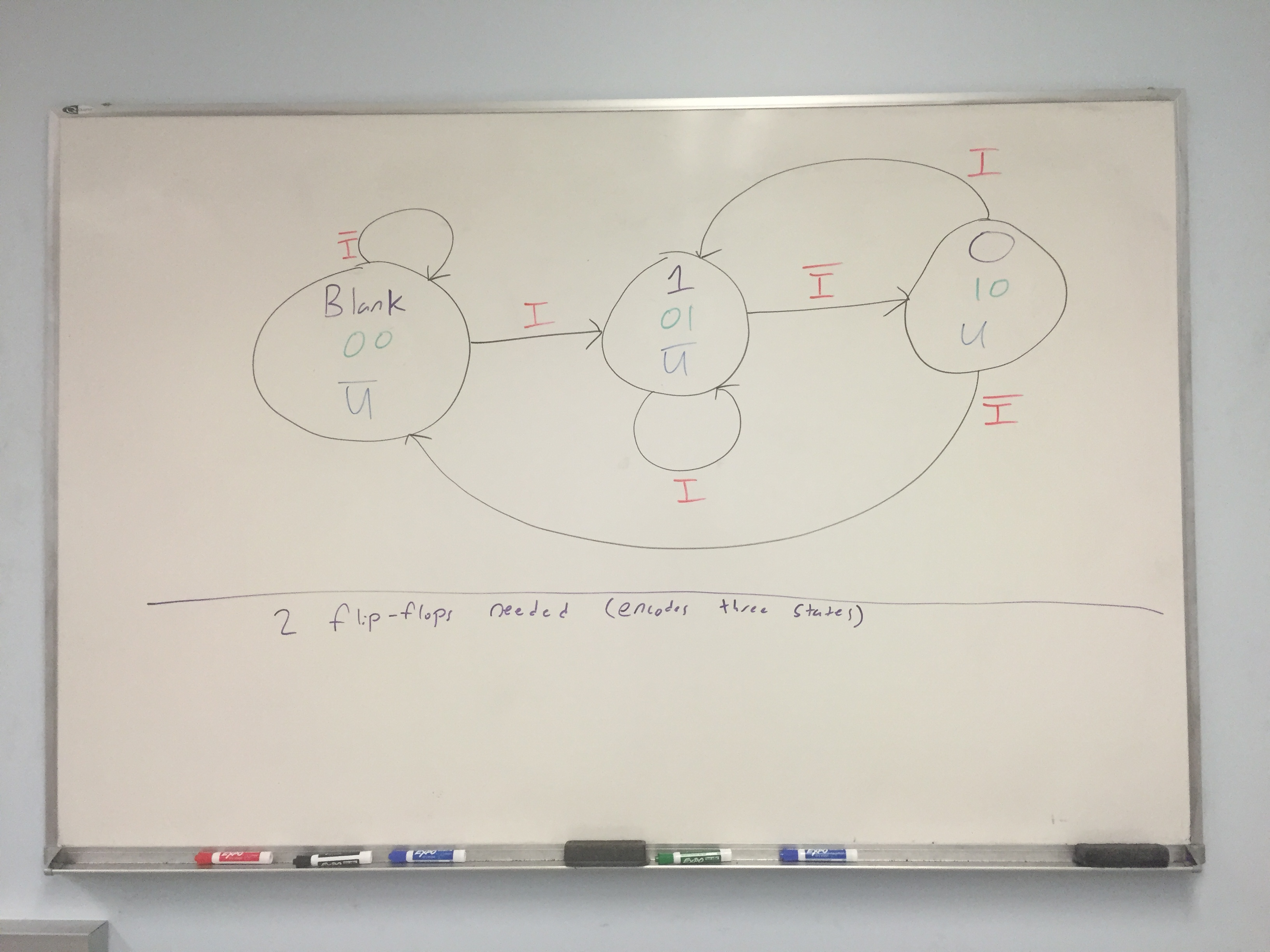
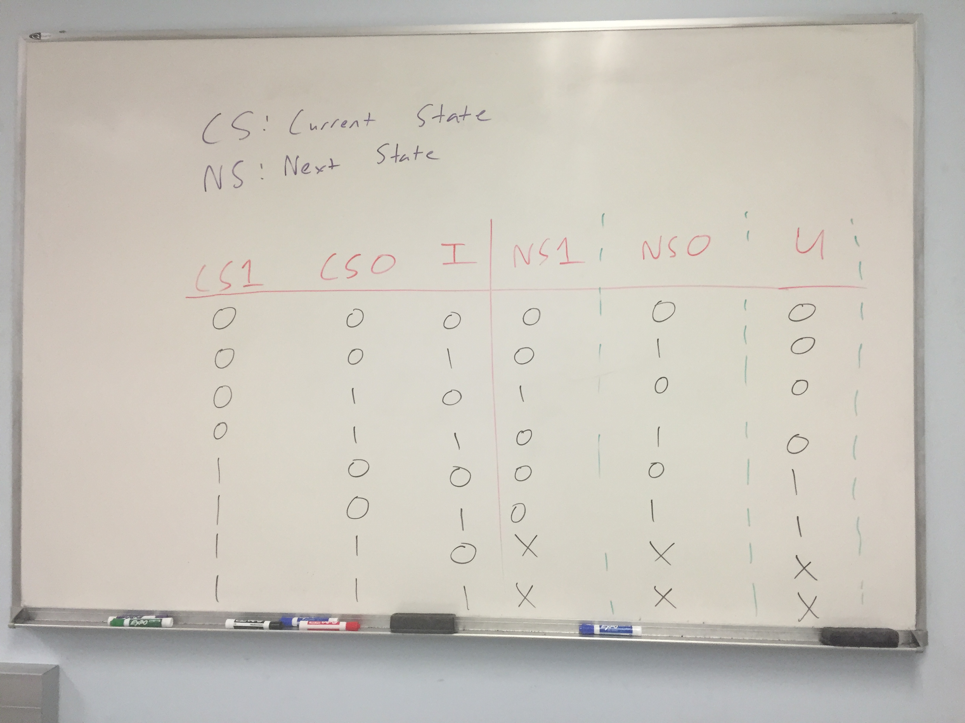
To help with questions 1-3, a solution to a very similar problem is provided.
The state diagram is here, and the corresponding truth table is here.
The only difference between Task 2 and this provided solution is that the provided solution recognizes 10 as opposed to 01.
0110
In this task, you will design a FSM which will set a particular output U to 1 each time 0110 is encountered in a stream of inputs.
Inputs are specified one at a time, and are represented by the variable I.
To illustrate, consider the following example, which shows different values of U and I over time, where each cell is separated by a clock tick:
I |
1 |
0 |
1 |
1 |
0 |
0 |
1 |
1 |
0 |
1 |
0 |
1 |
1 |
0 |
1 |
1 |
0 |
1 |
1 |
0 |
1 |
U |
0 |
0 |
0 |
0 |
0 |
1 |
0 |
0 |
0 |
1 |
0 |
0 |
0 |
0 |
1 |
0 |
0 |
1 |
0 |
0 |
1 |
In the above example, it may appear that the output of U is delayed with respect to input I.
That is, when the 1 is 0110 is encountered, it's not until the next clock tick that U is set to 1.
This is actually expected behavior, as it reflects the fact that first the circuit reads 1, and then it moves into a state that reports U = 1.
This overall task is separated into a series of questions.
Draw the finite state machine corresponding to this task.
If you are submitting this online, put this diagram ito a file named “sequence2.jpg”.
How many latches/flip-flops do you need to implement this state machine?
(Hint: this corresponds to the number of bits necessary in order to encode all possible states uniquely.)
If you are submitting this online, put this into a file named “sequence2.txt”.
This will be read by hand, so don't worry about the formatting (as long as it is clear and unambiguous).
Draw a single truth table representing the behavior of the state machine.
Be sure to label your states in binary.
Your table should have inputs corresponding to whatever state you are in, along with I.
The output corresponds to the next state to enter for a given input state, along with U.
If you are submitting this online, add this to your “sequence2.txt” file.
This will be read by hand, so don't worry about the formatting (as long as it is clear and unambiguous).
Using a Karnaugh map, determine the minimal sum-of-products formula corresponding to output U.
Where appropriate, use don't cares in the map (note that there may be no appropriate uses of don't cares).
If you are submitting this online, add this to your “sequence2.txt” file.
This will be read by hand, so don't worry about the formatting (as long as it is clear and unambiguous).
Using a Karnaugh map, determine the minimal sum-of-products formula corresponding to the rightmost bit of the next state.
Where appropriate, use don't cares in the map (note that there may be no appropriate uses of don't cares).
If you are submitting this online, add this to your “sequence2.txt” file.
This will be read by hand, so don't worry about the formatting (as long as it is clear and unambiguous).
Note the similarity between this task and Task 2. Task 3 ends up doing something very similar to both Task 2 and the example solution provided for the task similar to Task 2. That said, be sure to take into account the differences. Pay particularly close attention to where transitions should go which move “backwards” in the FSM. That is, it is expected that you'll have transitions which go to previously observed states, and these transitions won't necessarily all return to the same state.
You may either submit your pictures / scans on Canvas (for Lab 11), or submit it directly to me in class.
If you collaborated with anyone, be sure to submit collaborators.txt, where each line of the file lists a person you collaborated with.